Robotics in Launceston
2011-04-10 Wheel Encoders
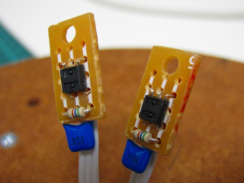 The wheel encoders are made from
scraps of proto board and are based on Hamamatsu P5587 digital
photoreflectors. The only other components needed are a 0.1uF
glitch filter capacitor and a 680R current limiting resistor for
the infrared diode. (The photoreflectors are powered directly by the
microcontroller's Port C pins 0 and 5. With this value of resistor
they draw less than 6mA which is well within the limit of 25mA per
GPIO pin of the PIC18F2620.) Normally a pull-up resistor would
also be required on the output but in this case it is connected to
the microcontroller's Port B which has internal pull-up resistors.
The wheel encoders are made from
scraps of proto board and are based on Hamamatsu P5587 digital
photoreflectors. The only other components needed are a 0.1uF
glitch filter capacitor and a 680R current limiting resistor for
the infrared diode. (The photoreflectors are powered directly by the
microcontroller's Port C pins 0 and 5. With this value of resistor
they draw less than 6mA which is well within the limit of 25mA per
GPIO pin of the PIC18F2620.) Normally a pull-up resistor would
also be required on the output but in this case it is connected to
the microcontroller's Port B which has internal pull-up resistors.
| Pin | Name | Mode | Title | Pin | Name | Mode | Title | |
|---|---|---|---|---|---|---|---|---|
| 1 | K | in | IR LED Cathode (Positive) | 6 | Vcc | in | 5 Volts | |
| 5 | GND | in | Ground | |||||
| 3 | A | in | IR LED Anode (Ground) | 4 | Vo | out | High on Light Detected |
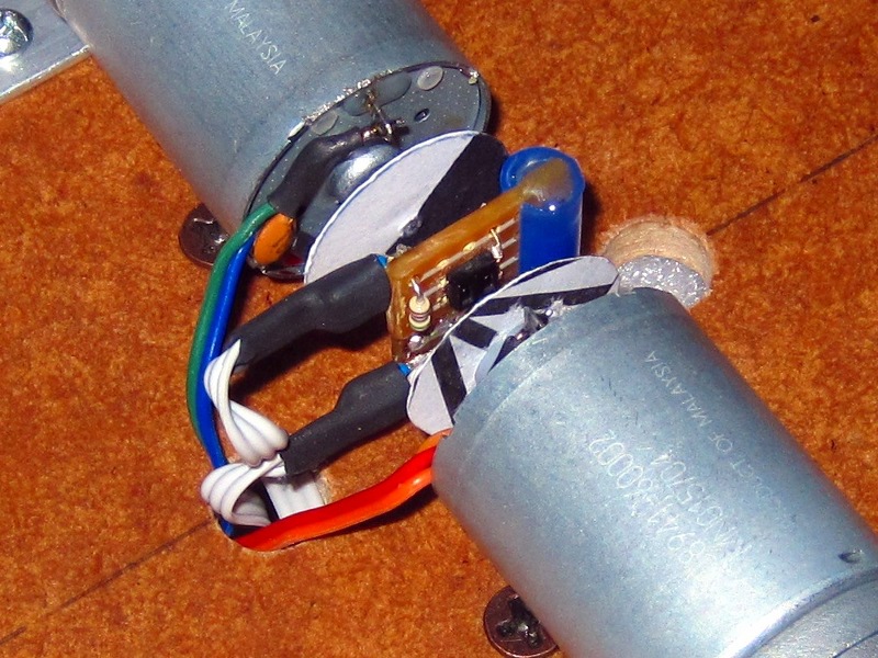 The wheel encoders are protected with a
small piece of heat shrink tubing and super-glued together along one
side, facing in opposite directions. They are held in place between
the encoder discs using a short length of stiff plastic tube cut
from the ink reservoir of an empty disposable pen. This is set into
a hole in the robot base and slit down one side to grip the edges
of the wheel encoders. Some hot melt glue keeps it all in place.
The wheel encoders are protected with a
small piece of heat shrink tubing and super-glued together along one
side, facing in opposite directions. They are held in place between
the encoder discs using a short length of stiff plastic tube cut
from the ink reservoir of an empty disposable pen. This is set into
a hole in the robot base and slit down one side to grip the edges
of the wheel encoders. Some hot melt glue keeps it all in place.
The encoder discs are cut from stiff card and half blacked out with a sharpie. They are mounted on the end of the motor shafts using nylon rollers from curtain hangers for reinforcement, and more hot glue. These will probably just be temporary as I intend to replace them with discs cut from the lid of a margerine container. This kind of stiff white plastic is very thin and highly reflective making it ideal for this application.
2011-03-28 Robot Controller
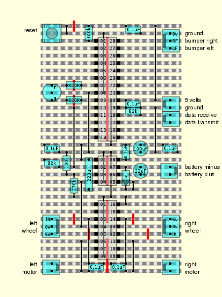 This is the layout for a small
robot controller which I designed and built a few years ago. The
robot that I designed it for wasn't terribly satisfactory, being
too small and unstable, so I've built a new and larger one to carry
it. The controller uses a PIC18F2620 microcontroller and a
SN754410 motor driver. Power is regulated by a MAX638
switching regulator. It still has five uncommitted general purpose
I/O pins available, and the pins for connecting to an I2C two wire
bus haven't been connected to anything yet either.
This is the layout for a small
robot controller which I designed and built a few years ago. The
robot that I designed it for wasn't terribly satisfactory, being
too small and unstable, so I've built a new and larger one to carry
it. The controller uses a PIC18F2620 microcontroller and a
SN754410 motor driver. Power is regulated by a MAX638
switching regulator. It still has five uncommitted general purpose
I/O pins available, and the pins for connecting to an I2C two wire
bus haven't been connected to anything yet either.
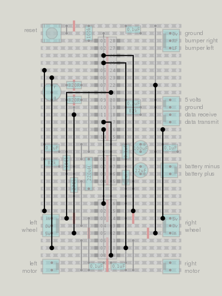 The PIC18F2620 has six
general purpose input/output pins connected to the SN754410
which is used as a dual full-H motor driver. Port A pins 1 and 2
control the direction of the right motor and Port A pins 3 and 4
control the direction of the left motor. Port C pins 1 and 2 enable or
disable the left and right motor drivers respectively. Internally pins
1 and 2 of Port C are controlled using the CCP (Capture/Compare/PWM)
modules of the controller which are configured for pulse width
modulation.
The PIC18F2620 has six
general purpose input/output pins connected to the SN754410
which is used as a dual full-H motor driver. Port A pins 1 and 2
control the direction of the right motor and Port A pins 3 and 4
control the direction of the left motor. Port C pins 1 and 2 enable or
disable the left and right motor drivers respectively. Internally pins
1 and 2 of Port C are controlled using the CCP (Capture/Compare/PWM)
modules of the controller which are configured for pulse width
modulation.
The remaining pins of Port C are reserved for the I2C bus and serial communications. Port A pins 5 and 7 are used as digital outputs to control the red and green LEDs and pin 6 is connected as a digital input to the low battery indicator of the MAX638 switching regulator. The internal pull up resistors of Port B are enabled and pins 6 and 7 are (to be) connected to bumper switches while pins 0 and 1 are connected to the outputs of the wheel sensors. Pins 0 and 5 of Port C are used to power the wheel sensors.
| Pin | Name | Mode | Title | Pin | Name | Mode | Title | |
|---|---|---|---|---|---|---|---|---|
| 1 | MCLR | in | Reset | 28 | RB7 | in | Bumper Right | |
| 2 | RA0 | 27 | RB6 | in | Bumper Left | |||
| 3 | RA1 | out | Right Motor Reverse | 26 | RB5 | |||
| 4 | RA2 | out | Right Motor Forward | 25 | RB4 | |||
| 5 | RA3 | out | Left Motor Reverse | 24 | RB3 | |||
| 6 | RA4 | out | Left Motor Forward | 23 | RB2 | |||
| 7 | RA5 | out | Red LED | 22 | RB1 | in | Wheel Sensor Left | |
| 8 | Vss | Ground | 21 | RB0 | in | Wheel Sensor Right | ||
| 9 | RA7 | out | Green LED | 20 | Vdd | in | 5 Volts | |
| 10 | RA6 | in | Battery Ok | 19 | Vss | Ground | ||
| 11 | RC0 | out | Wheel Power Left | 18 | RC7 | in | Receive Data | |
| 12 | RC1 | out | Motor Power Right | 17 | RC6 | out | Transmit Data | |
| 13 | RC2 | out | Motor Power Left | 16 | RC5 | out | Wheel Power Right | |
| 14 | RC3 | out | I2C Clock | 15 | RC4 | in/out | I2C Data |
| Pin | Name | Mode | Title | Pin | Name | Mode | Title | |
|---|---|---|---|---|---|---|---|---|
| 1 | 1,2EN | in | Enable Drivers 1 and 2 | 16 | VCC1 | in | Logic Supply Voltage | |
| 2 | 1A | in | Input 1 | 15 | 4A | in | Input 4 | |
| 3 | 1Y | out | Output 1 | 14 | 4Y | out | Output 4 | |
| 4 | GND | Heat Sink and Ground | 13 | GND | Heat Sink and Ground | |||
| 5 | GND | Heat Sink and Ground | 12 | GND | Heat Sink and Ground | |||
| 6 | 2Y | out | Output 2 | 11 | 3Y | out | Output 3 | |
| 7 | 2A | in | Input 2 | 10 | 3A | in | Input 3 | |
| 8 | VCC2 | in | Output Supply Voltage | 9 | 3,4EN | in | Enable Drivers 3 and 4 |
The MAX638 has a battery level sensor which triggers the low battery indicator when the voltage on pin 2 falls before 1.31 volts. The datasheet gives the formula R1=R2*(VLB/1.31-1) for calculating the values to use. Alternatively, the formula for low battery voltage given the values of R1 and R2 is VLB=1.31*(R1/R2+1). For the currently installed values of R1=675k and R2=97k this gives a low voltage threshold of 10.43 volts. With a pack of eight 1.2 volt NiMH AA batteries this may prove to be a bit conservative, given that fully charged they only yield 11 volts.
| Pin | Name | Mode | Title | Pin | Name | Mode | Title | |
|---|---|---|---|---|---|---|---|---|
| 1 | VOUT | in | Voltage Sense | 8 | COMP | in | Compensation | |
| 2 | LBO | out | Low Battery Indicator | 7 | VFB | in | Voltage Control | |
| 3 | LBI | in | Low Battery Detector | 6 | VS | in | Power | |
| 4 | GND | Ground | 5 | LX | out | Inductor Driver |
2011-03-23 Serial Interface
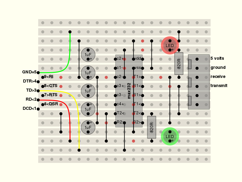 Since an RS232 interface is still the
easiest way to connect a computer to a microcontroller or robot,
I designed a small general purpose interface board around the
MAX232 that I could use for this purpose. On one side it
has a female DB9 connector and on the other side it has a pair of
male two pin polarised connectors which carry TD, RD and ground to
the microcontroller, and receive 5 volts from the microcontroller's
power supply.
Since an RS232 interface is still the
easiest way to connect a computer to a microcontroller or robot,
I designed a small general purpose interface board around the
MAX232 that I could use for this purpose. On one side it
has a female DB9 connector and on the other side it has a pair of
male two pin polarised connectors which carry TD, RD and ground to
the microcontroller, and receive 5 volts from the microcontroller's
power supply.
| Pin | Name | Mode | Title | Pin | Name | Mode | Title | |
|---|---|---|---|---|---|---|---|---|
| 1 | C1+ | out | Capacitor 1 Positive | 16 | Vcc | in | 5 Volts | |
| 2 | V+ | out | Voltage Out Positive | 15 | GND | Ground | ||
| 3 | C1- | out | Capacitor 1 Negative | 14 | T1out | out | Driver 1 Output (Line Level) | |
| 4 | C2+ | out | Capacitor 2 Positive | 13 | R1in | in | Receiver 1 Input (Line Level) | |
| 5 | C2- | out | Capacitor 2 Negative | 12 | R1out | out | Receiver 1 Output (Logic Level) | |
| 6 | V- | out | Voltage Out Negative | 11 | T1in | in | Driver 1 Input (Logic Level) | |
| 7 | T2out | out | Driver 2 Output (Line Level) | 10 | T2in | in | Driver 2 Input (Logic Level) | |
| 8 | R2in | in | Receiver 2 Input (Line Level) | 9 | R2out | out | Receiver 2 Output (Logic Level) |
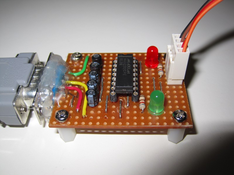 This is the RS232 Interface board that I
made for connecting my Linux workstation to a robot controller. The
red indicator LED shows the status of the TD signal (data received
from the computer) and the green indicator LED shows the status of
the RD signal (data transmitted to the computer). There is plenty
of room to connect either the RTS and CTS signals, or the DTR and
DSR signals should they be needed in the future.
This is the RS232 Interface board that I
made for connecting my Linux workstation to a robot controller. The
red indicator LED shows the status of the TD signal (data received
from the computer) and the green indicator LED shows the status of
the RD signal (data transmitted to the computer). There is plenty
of room to connect either the RTS and CTS signals, or the DTR and
DSR signals should they be needed in the future.
| Pin | Name | Mode | Title | Pin | Name | Mode | Title | |
|---|---|---|---|---|---|---|---|---|
| 1 | DCD | out | Data Carrier Detect | 6 | DSR | out | Data Set Ready | |
| 2 | RD | out | Receive Data | 7 | RTS | in | Request To Send | |
| 3 | TD | in | Transmit Data | 8 | CTS | out | Clear To Send | |
| 4 | DTR | in | Data Terminal Ready | 9 | RI | out | Ring Indicator | |
| 5 | GND | Common Ground |
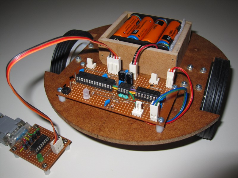 The interface board connected
to the controller of the minirover which I have been constructing
lately. The controller has a PIC18F2620 which has been
initialised with a bootloader that I wrote in C and compiled
with SDCC. The bootloader is very similar to the "official"
bootloader from Microchip. I've also written a C program for Linux for
uploading firmware to the microcontroller using the bootloader.
The interface board connected
to the controller of the minirover which I have been constructing
lately. The controller has a PIC18F2620 which has been
initialised with a bootloader that I wrote in C and compiled
with SDCC. The bootloader is very similar to the "official"
bootloader from Microchip. I've also written a C program for Linux for
uploading firmware to the microcontroller using the bootloader.
2011-02-22 Web Sites
The first thing that I am going to need to make this site really useful for my robotics experiments is a list of all the web sites that I use on a regular basis (bold text), or that I think I might need to use in future (plain text). As you can imagine these lists can't possibly be exhaustive, but I will try to keep them up to date. If you know of any robotics sites that I've missed, please let me know and I'll be happy to add them.
- Online Stores
- 4D Systems, Acroname, Adafruit Industries, Australian Robotics, Budget Robotics, Dimension Engineering, Dontronics, Element 14, Futurlec, Jaycar, Little Bird Electronics, Lynxmotion, Microchip, Oatley Electronics, Pololu Robotics & Electronics, Proto Advantage, RS Australia, Reynolds Electronics, Robot Electronics, Robot Gear, Robot Parts, Robot Shop, Robot Superstore, Robot e Shop, Robotis, Sedonia Technologies Ltd, Seeed Studio, Sparkfun Electronics, Tautic, Tin Can Tools, Toys Down Under, Tribotix
- News Sites
- Robots.Net
2011-02-19 Wheel Mounts
I just bought a pair of gear motors from Virtual Village on eBay and I am very pleased with them. Not only were they inexpensive but when they arrived yesterday they also turned out to be of high quality. However I still need to find a way to couple the D-shaft outputs of the gear motors to a robot drive train and after some searching, the only commercially available option appears to be relatively expensive. I ordered two pairs of Pololu 4mm universal aluminium mounting hubs from Robot Gear and now await their arrival.
 Having just spent as much for the wheel mounts
as I had spent for the gear motors themselves, it occurred to me that
maybe I should ask the experts on the Freenode IRC
#robotics channel. It turns out that rue_mohr published a
tutorial on how to make your own wheel mounts
and after taking a look at that I had another idea.
Having just spent as much for the wheel mounts
as I had spent for the gear motors themselves, it occurred to me that
maybe I should ask the experts on the Freenode IRC
#robotics channel. It turns out that rue_mohr published a
tutorial on how to make your own wheel mounts
and after taking a look at that I had another idea.
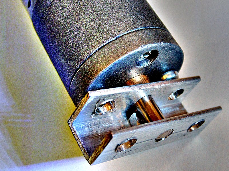
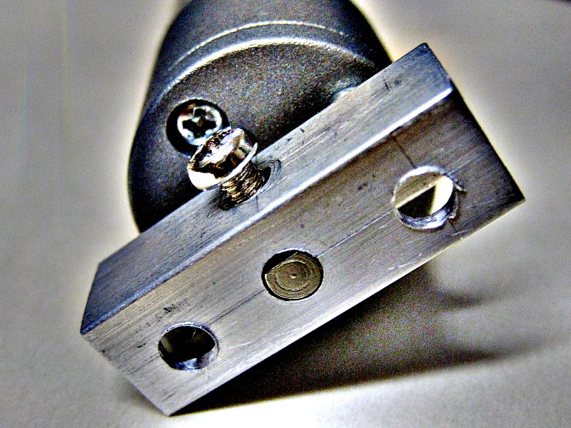 Using a piece of left over 10mm aluminium
U-channel from my junk box, and an M3 nut and screw, I was able
to avoid having to do any metal bending or thread cutting. These
photos are just of a rough prototype... for the final version I will
probably have to trim some corners off to make sure there is enough
clearance between the body of the gearbox and the wheel mounting.
Using a piece of left over 10mm aluminium
U-channel from my junk box, and an M3 nut and screw, I was able
to avoid having to do any metal bending or thread cutting. These
photos are just of a rough prototype... for the final version I will
probably have to trim some corners off to make sure there is enough
clearance between the body of the gearbox and the wheel mounting.
2011-02-18 Introduction
After many years of just thinking about it I've finally started a website dedicated to robotics (this one). There are already many useful and entertaining robotics websites on the net and it is not my intention to create yet another one. Instead, I am going use this website to gather all the information that I find useful and interesting, and also to report on my own robotics activities, such as they are.
My motivation for doing this is that there is so much information available on the internet concerning robotics that it is becoming increasingly difficult to keep track of it all. By collecting and organising that which I find relevant to my projects here, I hope to be able to make better sense of it. By publishing what amounts to my lab notebook on the internet, maybe it will also help and encourage some other aspiring roboticists too.
Previously I've been publishing a little bit about what I've done on my home page but the format didn't lend itself to frequent updates and it has been sorely neglected in recent years. Over time I expect to update that material and migrate it to this site.
Copyright 2011 by Andrew Smith